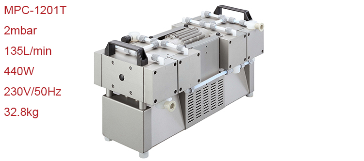
Grouped equipment
MPC series diaphragm pump
The MPC series diaphragm pump is a highly precise instrument that follows the following principles before use.

MPC-1201T diaphragm pump
Installation and connection
1. Place the diaphragm pump on a flat, level surface.
2. Remove the protective cap from the suction and pressure ports.
3. Prepare to connect.
4. Connect the vacuum connector to the suction port.
5. Connect the exhaust pipe to the pressure fitting.
6. Connect the diaphragm pump to the power supply.
Daily maintenance requirements
Check the pump daily for abnormal operating noise and accumulate heat on the pump surface.
We recommend replacing the diaphragm after 10,000 working hours. Users can specify to switch earlier, depending on the application process.
Check the electrical and vacuum connections daily.
Pump design
The diaphragm pump consists of a pump casing and a drive motor.
The pump housing contains a drive unit and four pump heads. Each pump head contains a diaphragm and a working valve. The two pairs of pump heads are arranged opposite each other.
The pump head is driven by an eccentric shaft with a connecting rod.
Class 1 to 4 pumps are available depending on the circuit of the pump head.
Operating principle
The motor, eccentric shaft and connecting rod set the diaphragm in the stroke motion. This changes the amount of space between the diaphragm and the pump head (pump chamber). When the outlet valve is closed (intake process), increase the size of the pump chamber to open the intake valve.
Reducing the size of the pump chamber will vent the gas through the outlet valve.
The valve is driven by the pumped gas. Most of the fluid in the diaphragm pump minimizes pumping efficiency.
Send Us Message
Your message was sent successfully.
Sorry!Something Went Wrong.
